 |
|
|
|
|
|
|
|
|
|
|
|
|
|
|
|
|
|
|
|
|
|
|
|
|
|
|
|
|
|
|
|
|
|
|
|
|
|
|
|
|
|
|
|
|
|
|
|
|
|
|
|
|
|
|
|
|
|
|
|
LUGER WINDWARD BLUEPRINT DIAGRAMS
Circa 1973
A note from Agent Pat: All the diagrams you find here were copied from original Luger Assembly Plans (blueprints). The 24 x 36 inch documents were so old and faded that each diagram had to be redrawn and digitally enhanced before it could be scanned, to remove most of the discoloration for easier viewing.
This lengthy restoration project was undertaken by
Patrick "Agent Pat" Harrington
Pat began redrawing the blueprints because he is restoring a
1969 Luger Windward 20 Sloop
A note from Joanie and The Luger Sailboat Mooring: My involvement in this project started after Pat uploaded the Windward information onto his homepage website. I wanted to make the diagrams easier to view on the internet by enhancing them with color. In some cases I've re-written the text for clarification so the images could stand alone (without the step-by-step and part-by-part assembly directions).
I began augmenting* Pat's diagrams to complement the work he started,
and to make the information available on
The Luger Sailboat Mooring
www.lugerboats.com
You can e-mail "Agent Pat" with comments about his diagrams,
or his Windward restoration project at:
pharring@ksip.net
You can e-mail me with comments or questions
about this project's "Second Phase" at:
blueprints@lugerboats.com
* Each of the redrawn figures was "contrast enhanced" and "airbrushed" with color to make the images easier to view on a monitor. Most blueprint diagrams are self explanatory, and do not need the added "Assembly Instruction" text. It seemed easier to have a listing of the diagram "Figure Numbers", an explanation of what information each diagram depicted, and a list of the major Part Numbers.
Some of the more popular diagrams have been highlighted in BOLD text.
|
|
|
|
|
|
|
|
|
|
|
|
|
|
Standing Rigging Diagrams
|
|
|
|
|
|
|
|
|
 |
|
|
|
|
|
|
|
Diagram Description
Rigging hardware placement
Placement of mast base and chainplates
Template for location of holes
Clew attachment with backer blocks
Stem Head Fitting
Cut 3/8" taper to the base of mast
Mast & Accessories Assembly
Jib Halyard Attachment
Boom End Assembly
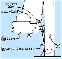
Boom cleat attachment & sail slot cut-out
Downhaul cleat attachment
Cross section for downhaul cleat attachment
Spreader Bar Assembly
Mainsail outhaul and boom end assembly
Mainsheet Path
Mainsail halyard path at masthead
Upper and lower shroud attachment at hull
Jib & Forestay attachment to
Stem Head Fitting
Boom, Gooseneck, Down Haul Assembly
Traveler Line Attachment
Mainsail to mast (parts and attachment)
Jib sail line attachment to jib
Jib Sail to Halyard Attachment
Rigging diagram - fore and aft views
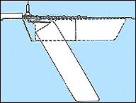
Windward on Trailer - side view diagram
Rigging diagram - side view
Rigging Diagram - side view - close-ups
Masthead light installation
|
|
|
|
|
|
|
|
|
|
|
|
|
|
|
|
|
|
|
|
|
|
|
|
|
Major Rigging Part Numbers
Part 02 - Mast Head Casting
Part 04 - Mast Base
Part 05 - Nylon Sheave
Part 07 - Upper Shroud & Tang
Assemblies
Part 11 - Hound Assembly
Part 15 - Swing Spreader Bracket
Part 16 - Spreader Bar Tang
Assembly
Part 18 - Cleat
Part 24 - Gooseneck casting
Part 28 - Aluminum Boom Extrusion
Part 29 - Outhaul Casting
Part 30 - Tang
Part 31 - Becket Block
Part 32 - Single Swivel Block
Part 33 - SS Strap
Part 36 - Chain Plate
Part 35 - Channel Stay Adjuster
Part 42 - Stem Head Fitting
Part 43 - Cleat
Part 49 - Shackle
|
|
|
|
|
|
|
|
|
|
|
 |
|
|
|
|
|
|
|
|
|
|
|
|
|
|
|
|
|
Diagram Description
Cable path from spool
Cable to Keel Attachment - assembly of parts
Cable to keel attachment - side view
Insertion and attachment of keel within housing
Fiberglass bonding
Keel Housing
Keel and Winch Reinforcing
Apply Bonding Material to Housing area
Proper positioning of keel winch spool and frame
Keel Measurements
Centering Winch Cable on Spool
|
|
|
|
|
|
|
|
|
|
|
|
|
|
|
|
|
|
|
Major Swing Keel Part Numbers
Part 1 - Pulley
Part 5 - Cable, Swing Keel
Part 12 - Swing Keel
Part 13 - Hinge, Swing Keel
Part 23 - Winch Spool
Part 300 - Hull, bottom
|
|
|
|
|
|
|
|
|
|
|
|
|
|
|
|
|
|
General Assembly Diagrams
|
|
|
|
|
|
|
|
|
 |
|
|
|
|
|
|
|
|
|
|
|
Diagram Description
Attaching components with screws
Attaching components with screws
Repair damage to moulded fiberglass areas
Bonding parts using 2-layers of bonding material
Construction of Assembly Cradle
Preparation of Hull for Centerboard Well
Cross section of centerboard well attachment
Preparation for window installation
Window glazing and gasket installation
Fiberglass component assembly
Close-Up - Attaching hull sections
Attachment of transom
Proper attachment of fiberglass components
Proper attachment of bow components
Cross section of proper and improper installation
Three layer bonding of 6" wide material
Two layer bonding of 4" wide material
Two layer bonding of 4" material
Bow eye reinforcement
Bow eye and winch spool placement
Assembly of component parts
Reinforcement of fiberglass Part 304
Hatch Cut Out Reinforcement
Reinforcement of fiberglass Part 305
Close-Up of Part 305 Hatchway Reinforcement
Assembling & Bonding Parts 302, 304 and 305
Trimming part 305
Centerboard Well Assembly & Reinforcement
Centerboard assembly (Windward model)
Installation & Positioning of Centerboard
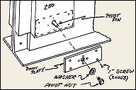
Cross section of well for pivot bolt positioning
Centerboard Well Cap Installation
Cross section of lower centerboard well section
|
|
|
|
|
|
|
|
|
|
|
|
|
|
Major Assembly Part Numbers
Part 201 - Centerboard Cap
Part 212 - Mast Support (wood)
Part 300 - Hull, Bottom
Part 301 - Side Panel (fiberglass)
Part 302 - Side Panel (fiberglass)
Part 303 - Transom
Part 306 - Cabin Top (fiberglass)
Part 307 - Centerboard Well, Right
Part 308 - Centerboard Well, Left
|
|
|
|
|
|
|
|
|
|
|
|
|
|
|
|
|
|
|
The "Harrington Project" was undertaken by Joanie Johnston. Pat "Agent Pat" Harrington had
redrawn blueprint diagrams, and Joanie Johnston later enhanced and altered diagrams
to make them easier to understand on a small format (computer monitor).
The enhanced drawings are an exclusive feature of The Luger Sailboat Mooring
|
|
|
|
|
|
|
|
|
|
 |
|
|
|
|
|
|
|
|
© 2006 j. rilling johnston all rights reserved
|
|
|
|
|
|